DMM Series Microelectromechanical Systems (MEMS) Wide-Band Microphones
PUI Audio™
Unit of Measure
| Items |
 /Asset/DMM-4026-B-I2S-EB-R.png /Asset/DMM-4026-B-I2S-EB-R.png DMM-4026-B-I2S-EB-R DMM Series -86 Decibels (dB) Power Supply Rejection Microelectromechanical Systems (MEMS) Wide-Band Microphone List Price {QUOTE}
|
 /Asset/DMM-4026-B-I2S-R.png /Asset/DMM-4026-B-I2S-R.png DMM-4026-B-I2S-R DMM Series -86 Decibels (dB) Power Supply Rejection Microelectromechanical Systems (MEMS) Wide-Band Microphone List Price {QUOTE}
|
 /Asset/DMM-4326-T-WP-R.png /Asset/DMM-4326-T-WP-R.png DMM-4326-T-WP-R DMM Series -80 Decibels (dB) Power Supply Rejection Microelectromechanical Systems (MEMS) Wide-Band Microphone List Price {QUOTE}
|
|||
| Manufacturer Stock | N/A {0} | N/A {0} | N/A {0} | |||
| Description |
N/A
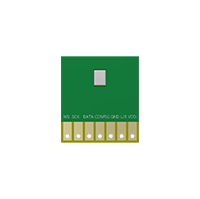
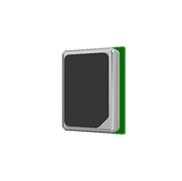
PUI Audio? is proud to release a line of high-fidelity MEMS wide-band microphones that cover the entire audio band from 20 Hz up to 18 kHz and up to 20 kHz on some models while featuring an industry-best consistency of ?1 dB across the entire frequency response. Quickly test and prototype the I2S DMM-4026-B-I2S-R with this evaluation board. Solder pads make wiring to the evaluation board quick-and-easy! |
N/A | N/A | |||
| Brands | N/A PUI Audio™ | |||||
| Manufacturer | N/A PUI Audio�, Inc. | |||||
| Directivity | N/A Omni-Directional | |||||
| Data Format | N/A I2S 24-bit data size with 18-bit precision, 32-bit word size | N/A I2S 24-bit data size with 18-bit precision, 32-bit word size | N/A 1/2 Cycle PDM | |||
| Sensitivity | N/A -26 dB | |||||
| Sensitivity Tolerance (±) | N/A 1 dB | |||||
| Testing Condition for Sensitivity | N/A 1 kHz at 50 cm with 94 dB source 0 dB=1 V/Pa | |||||
| Direct Current (DC) Rated Voltage | N/A 1.8 V | |||||
| Direct Current (DC) Operating Voltage Range | N/A 1.5 to 3.6 V | N/A 1.5 to 3.6 V | N/A 1.6 to 3.6 V | |||
| Supply Current at Normal Mode | N/A 820 ~ 1000 µA | N/A 820 ~ 1000 µA | N/A | |||
| Supply Current at Sleep Mode (Clock Off) | N/A 5 µA | N/A 5 µA | N/A | |||
| Current Draw at Full Power Mode | N/A | N/A | N/A 800 ~ 1000 µA | |||
| Current Draw at Low Power Mode | N/A | N/A | N/A 400 ~ 450 µA | |||
| Signal to Noise Ratio | N/A 64 dB | N/A 64 dB | N/A | |||
| Signal to Noise Ratio at Full Power Mode | N/A | N/A | N/A 58 dB | |||
| Signal to Noise Ratio at Low Power Mode | N/A | N/A | N/A 56 dB | |||
| Note for Signal to Noise Ratio | N/A 1 kHz, 94 dB input, A-Weighted | |||||
| Frequency Range | N/A 20 ~ 10000 Hz | N/A 20 ~ 10000 Hz | N/A | |||
| Frequency Range (-10 dB) | N/A | N/A | N/A 20 ~ 15000 Hz | |||
| Total Typical Harmonic Distortion | N/A 1 % | N/A 1 % | N/A 0.5 % | |||
| Testing Condition for Total Typical Harmonic Distortion | N/A 110 dB at 50 cm, 1 kHz acoustic source | N/A 110 dB at 50 cm, 1 kHz acoustic source | N/A 94 dB at 50 cm, 1 kHz acoustic source | |||
| Startup Time (Sensitivity Reaching 90% of Listed Value From Initial Power-Up) | N/A 20 ms | N/A 20 ms | N/A | |||
| Startup Time (From Sleep Mode) | N/A 20 ms | N/A 20 ms | N/A | |||
| Startup Time (From Normal Mode to Sleep Mode) | N/A 20 ms | N/A 20 ms | N/A | |||
| Input Clock Frequency at Normal Mode | N/A 2.048 ~ 4.096 MHz | N/A 2.048 ~ 4.096 MHz | N/A | |||
| Input Clock Frequency at Sleep Mode | N/A 320 kHz | N/A 320 kHz | N/A | |||
| Clock Jitter (Long Term Root Mean Square (RMS)) | N/A 500 ps | N/A 500 ps | N/A | |||
| Load Capacitance | N/A 140 pF | |||||
| Pass Band (Fs = 48 kHz) | N/A 18 kHz | N/A 18 kHz | N/A | |||
| Pass Band Attenuation | N/A 0.5 dB | N/A 0.5 dB | N/A | |||
| Acceptable Soldering Methods | N/A | N/A Reflow Solder | N/A Reflow Solder | |||
| Acoustic Overload Point (AOP) at Full Power Mode | N/A | N/A | N/A 123 dB | |||
| Acoustic Overload Point (AOP) at Low Power Mode | N/A | N/A | N/A 120 dB | |||
| Testing Condition for Acoustic Overload Point (AOP) at Low Power Mode | N/A | N/A | N/A 10 % THD at 1 kHz, acoustic source 50cm away from microphone | |||
| Environmental Compliances | N/A Restriction of Hazardous Substances (RoHS)/Halogen Free | |||||
| Power Supply Rejection1 | N/A -86 dB | N/A -86 dB | N/A -80 dB | |||
| Testing Condition for Power Supply Rejection | N/A 100 mVpp Square Wave at 217 Hz, A-Weighted | |||||
| Weight | N/A | N/A < 0.3 g | N/A < 0.3 g | |||
| Maximum Direct Current (DC) Voltage on Any Pin | N/A | N/A | N/A 4 V | |||
| Maximum Sound Pressure Level (SPL) Before Damage (Source 50 cm From Microphone) | N/A | N/A | N/A 160 dB | |||
| Maximum Mechanical Shock | N/A | N/A | N/A 10000 G | |||
| Maximum Vibration | N/A | N/A | N/A Pre-MIL-STD-883 Method 2007, Test Condition B | |||
| Operating Temperature (VDD < 3 VDC) | N/A | N/A | N/A -40 ~ +100 ºC | |||
| Operating Temperature (VDD > 3 VDC) | N/A | N/A | N/A -40 ~ +70 ºC | |||
| Operating Temperature | N/A -40 ~ +100 ºC | N/A -40 ~ +100 ºC | N/A | |||
| Storage Temperature | N/A -40 ~ +125 ºC | |||||
| Ingress Protection Rating | N/A | N/A | N/A Ingress Protection (IP57) | |||
| Moisture Sensitivity Level (MSL)2 | N/A | N/A 1 | N/A 1 | |||
| Clock Frequency at Sleep Mode | N/A | N/A | N/A 0 ~ 320 kHz | |||
| Clock Frequency at Low Power Mode | N/A | N/A | N/A 351 ~ 800 kHz | |||
| Clock Frequency at Full Power Mode | N/A | N/A | N/A 1.024 ~ 4.096 MHz | |||
| Duty Cycle | N/A | N/A | N/A 45 ~ 55 % | |||
| Testing Condition for Duty Cycle | N/A | N/A | N/A For fCLK ≤ 2.4 MHz the duty cycle must be in the range of 40 ~ 60% and for fCLK > 2.4 MHz the duty cycle must be 50% | |||
| High Logic Input | N/A | N/A | N/A 0.65 x VDD ~ VDD + 0.3V | |||
| Low Logic Input | N/A | N/A | N/A -0.3 ~ 0.35 x VDD | |||
| High Logic Output | N/A | N/A | N/A 0.65 x VDD ~ VDD + 0.3V | |||
| Low Logic Output | N/A | N/A | N/A -0.3 ~ 0.35 x VDD | |||
| Simulated Reflow (Without Solder) | N/A Samples for qualification testing require 3 passes 260 ±5 ºC reflow solder profiles. 2 hours of setting time is required between each reflow profile test. | N/A Samples for qualification testing require 3 passes 260±5 ℃ reflow solder profiles. 2 hours of setting time is required between each reflow profile test. | N/A Samples for qualification testing require 3 passes 260±5 ºC reflow solder profiles. 2 hours of setting time is required between each reflow profile test. | |||
| Static Humidity | N/A Precondition at +25 ºC for 1 hour. Expose to +85 ºC with 85% relative humidity for 1000 hours. Dry at room ambient for 3 ±1 hour before taking final measurement. | N/A Precondition at +25℃ for 1 hour. Expose to +85℃ with 85% relative humidity for 1000 hours. Dry at room ambient for 3 ±1 hour before taking final measurement. | N/A Precondition at +25 ºC for 1 hour. Expose to +85 ºC with 85% relative humidity for 1000 hours. Dry at room ambient for 3±1 hour before taking final measurement. | |||
| Temperature Shock | N/A Each cycle shall consist of 30 minutes at -40ºC, 30 minutes at +125ºC with 5 minutes transition time. Test duration is for 30 cycles, starting from cold to hot temperature. | N/A Each cycle shall consist of 30 minutes at -40℃, 30 minutes at +125℃ with 5 minutes transition time. Test duration is for 30 cycles, starting from cold to hot temperature. | N/A Each cycle shall consist of 30 minutes at -40 ºC, 30 minutes at +125 ºC with 5 minutes transition time. Test duration is for 30 cycles, starting from cold to hot temperature. | |||
| Electrostatic-Sensitive Device (ESD) Sensitivity | N/A Perform ESD sensitivity threshold measurements for each contact according to MIL-STD-883G, Method 3015.7 for Human Body Model. Identify the ESD threshold levels indicating passage of 8000V Human Body Model. | |||||
| Vibration Test | N/A Vibrate randomly along three perpendicular directions for 30 minutes in each direction, 4 cycles from 20~2000 Hz with a peak acceleration of 20 Gs. | |||||
| Shock Test | N/A Subject samples to half-sine shock pulses (3000±15% Gs for 0.3ms) in each direction, for a total of 18 shocks. | |||||
| Drop Test | N/A Drop samples from 1.5m height onto a steel surface, total 18 times and inspected for mechanical damage. | |||||
| Operation Life | N/A Subject samples to +125ºC for 168 hours under full maximum rated voltage. | N/A Subject samples to +125℃ for 168 hours under full maximum rated voltage. | N/A Subject samples to +125ºC for 168 hours under full maximum rated voltage. | |||
| Waterproof Test | N/A | N/A | N/A Place 15 microphones in water at 1m depth for 30 minutes. Remove and dissect 5 pieces to check for water ingress. Test remaining 10 microphones for sensitivity after resting at room temperature for 2 hours. | |||
| Note for Reliability Testing | N/A Microphone frequency response and sensitivity shall not deviate more than ±3 dB. | |||||
| Tolerance (±) | N/A 0.5 mm | |||||
| Angle Tolerance (±) | N/A 3 º | |||||
| Note | N/A Specifications subject to change or withdrawal without notice. | |||||
|
||||||
We use cookies to ensure that we give you the best experience on our website. If you continue to use this site we will assume that you are happy with it.Ok
