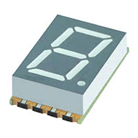
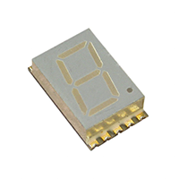
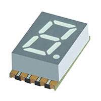
Surface Mount Displays
LED Displays
Common Anode, Right Hand Decimal.
A Relative Humidity between 40% and 60% is recommended in ESD-protected work areas to reduce static build-up during assembly process.
A Relative Humidity between 40% and 60% is recommended in ESD-protected work areas to reduce static build-up during assembly process.
Unit of Measure
| Items |
 /Asset/XZFBGA10A.jpg /Asset/XZFBGA10A.jpg XZFBGA10A 120 Milliwatt (mW) Power Dissipation (PD) Surface Mount Display List Price {QUOTE}
|
 /Asset/XZFMG10A.png /Asset/XZFMG10A.png XZFMG10A 62.5 Milliwatt (mW) Power Dissipation (PD) Surface Mount Display List Price {QUOTE}
|
 /Asset/XZFVG07A.jpg /Asset/XZFVG07A.jpg XZFVG07A 75 Milliwatt (mW) Power Dissipation (PD) Surface Mount Display List Price {QUOTE}
|
|||
| Manufacturer Stock | N/A {0} | N/A {0} | N/A {0} | |||
| Description |
N/A
Common Anode, Right Hand Decimal. A Relative Humidity between 40% and 60% is recommended in ESD-protected work areas to reduce static build-up during assembly process. |
|||||
| Brands | N/A SunLED | |||||
| Manufacturer | N/A SunLED | |||||
| Reverse Voltage (VR) | N/A 5 V | |||||
| Forward Current (IF) | N/A 30 mA | N/A 25 mA | N/A 30 mA | |||
| Forward Peak Current 1/10 Duty Cycle 0.1 Millisecond (ms) Pulse Width (iFS) | N/A 100 mA | N/A 140 mA | N/A 150 mA | |||
| Power Dissipation (PD) | N/A 120 mW | N/A 62.5 mW | N/A 75 mW | |||
| Operating Temperature (TA) | N/A -40 ~ +85 ºC | |||||
| Storage Temperature Range (TSTG) | N/A -40 ~ +85 ºC | |||||
| Electrostatic Discharge Threshold (HBM) | N/A 1000 V | N/A | N/A | |||
| Lead Solder Temperature (2 Millimeter (mm) Below Package Base) | N/A 260 ºC for 3 to 5 Seconds | N/A | N/A | |||
| Typical Forward Voltage (VF) at IF=10 Milliampere (mA) Current | N/A 3.05 V | N/A 2 V | N/A 2 V | |||
| Maximum Forward Voltage (VF) at IF=10 Milliampere (mA) Current | N/A 4 V | N/A 2.4 V | N/A 2.45 V | |||
| Maximum Reverse Current (IR) at VR=5 Volt (V) Voltage | N/A 10 µA | |||||
| Typical Wavelength of Peak Emission with CIE127-2007 (λP) at IF=10 Milliampere (mA) Current | N/A 520 nm | N/A 565 nm | N/A 574 nm | |||
| Typical Wavelength of Dominant Emission with CIE127-2007 (λD) at IF=10 Milliampere (mA) Current | N/A 530 nm | N/A 568 nm | N/A 570 nm | |||
| Typical Spectral Line Full Width at Half-Maximum (Δλ) at IF=10 Milliampere (mA) Current | N/A 35 nm | N/A 30 nm | N/A 20 nm | |||
| Typical Capacitance (C) at VF=0 Volt (V) Voltage, f= 1 Megahertz (MHz) Frequency | N/A 100 pF | N/A 15 pF | N/A 15 pF | |||
| Emitting Color | N/A Green | |||||
| Emitting Material | N/A Indium Gallium Nitride (InGaN) | N/A Gallium Phosphide (GaP) | N/A Aluminum Gallium Indium Phosphide (AlGaInP) | |||
| Minimum Luminous Intensity at IF= 10 Milliampere (mA) Current | N/A 21000 mcd | N/A 2200 mcd | N/A 3600 mcd | |||
| Minimum Luminous Intensity with CIE127-2007 at IF= 10 Milliampere (mA) Current | N/A 9000 mcd | N/A 560 mcd | N/A 1400 mcd | |||
| Typical Luminous Intensity at IF= 10 Milliampere (mA) Current | N/A 59990 mcd | N/A 4690 mcd | N/A 11990 mcd | |||
| Typical Luminous Intensity with CIE127-2007 at IF= 10 Milliampere (mA) Current | N/A 18990 mcd | N/A 1190 mcd | N/A 3090 mcd | |||
| Note for Luminous Intensity and Wavelength | N/A Luminous intensity value and wavelength are in accordance with CIE127-2007 standards. | |||||
| Digit Height | N/A 0.4 in | N/A 0.4 in | N/A 0.3 in | |||
| Tolerance (±) | N/A 0.25 mm0.01 in | |||||
| Moisture Sensitivity Level (MSL) | N/A 2a | |||||
| Units Per Package | N/A 400 | N/A 400 | N/A 550 | |||
| Package Type | N/A Reel | |||||
| Industry Standards | N/A Restriction of Hazardous Substances (RoHS) Compliant | |||||
| Features |
N/A
|
N/A
|
N/A
|
|||
| Note |
N/A
|
|||||
|
|
||||||
We use cookies to ensure that we give you the best experience on our website. If you continue to use this site we will assume that you are happy with it.Ok
